Using Lots of Geo in Physics
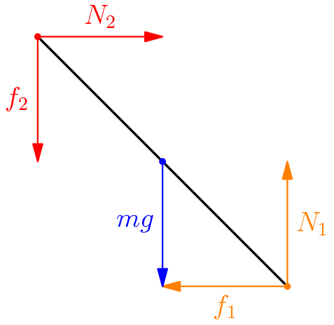
Physics Cup 2012 Problem 10: A thin rod of mass $m$ and length $L$ is placed into a corner formed by a vertical wall and a horizontal floor so that the rod forms an angle $\alpha$ with the floor and is perpendicular to the line where the floor and the wall meet. The static coefficient of friction of the rod against the wall and against the floor is $\mu=\tan\beta$, which is not large enough for keeping the current position – as long as the only forces applied to the rod are the normal and and friction forces applied to its endpoints, and the gravity force $mg$ applied to its centre. What is the minimal additional force $F$ needed for maintaining the current position of the rod (assuming that its direction and application point are optimal)? Express your answer in terms of $m$, $g$, $\alpha$, and $\beta$.
\begin{center}
    \begin{asy}
        import graph;
        size(5cm, 5cm);

        draw((1, 0) -- (0, 1), linewidth(1));

        draw((0, 1) -- (0, 0.5), arrow = Arrow, red);
        label(("$f_2$"), (0, 0.75), W, red);

        draw((0, 1) -- (0.5, 1), arrow = Arrow, red);
        label(("$N_2$"), (0.25, 1), N, red);

        draw((1, 0) -- (0.5, 0), arrow = Arrow, orange);
        label(("$f_1$"), (0.75, 0), S, orange);

        draw((1, 0) -- (1, 0.5), arrow = Arrow, orange);
        label(("$N_1$"), (1, 0.25), E, orange);

        draw((0.5, 0.5) -- (0.5, 0), arrow = Arrow, blue);
        label(("$mg$"), (0.5, 0.25), W, blue);

        dot((1, 0), orange);
        dot((0.5, 0.5), blue);
        dot((0, 1), red);
    \end{asy}
\end{center}

Solution
From dimensional analysis, we know that $F$ will take the form of
\[F = mg\, f \left (\alpha , \beta \right )\]Here, $f \left ( \alpha , \beta \right )$ is a function of the two variables. Our goal is to find this function.
I’m going to go off on a whim here and say that this problem’s write up will include more of my own thoughts on how I would have approached this problem if it showed up on an actual competition, so it’s probably going to differ from a formal write up, which is what most people would write for a formal solution, which is probably what you’ll find online.
Using the main \textit{purpose} of the problem is to minimize the extra force we need to apply. Therefore, it makes sense that the frictional forces are at their maximal value. Therefore,
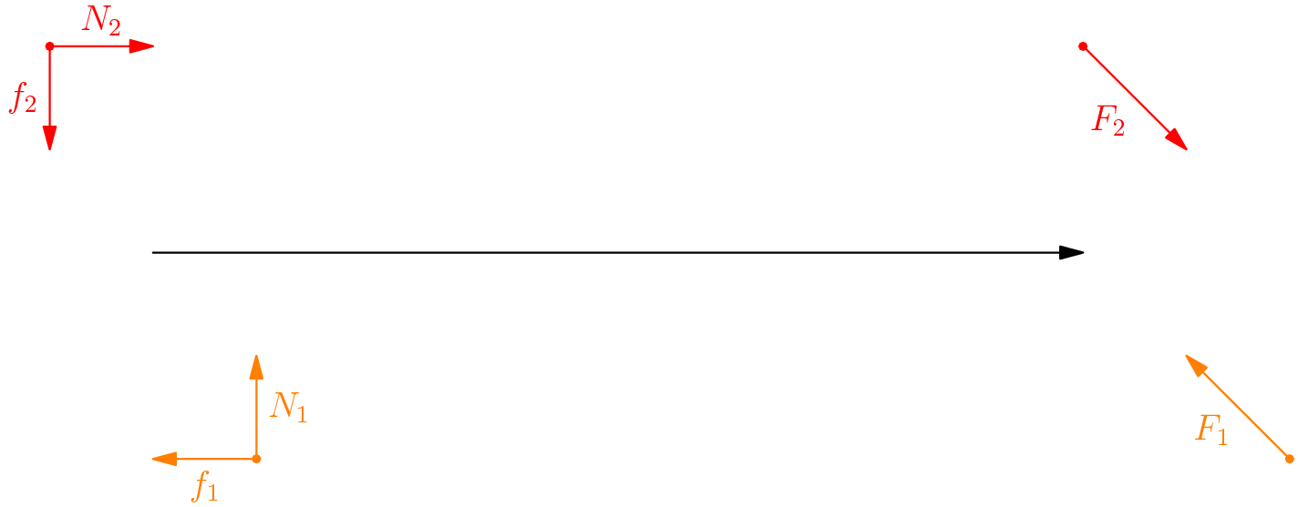
\[f_i = \mu N_i = N_i \tan{\beta}\]We can now use the method of generalized forces $F_1$ and $F_2$, combining the normal and frictional forces for each end of the rod. This allows us to finish the problem with less computation and less algebra.
\begin{center}
    \begin{asy}
        import graph;
        size(15cm);
        int offset = 5;

        draw((0, 2) -- (0, 1.5), arrow = Arrow, red);
        label(("$f_2$"), (0, 1.75), W, red);

        draw((0, 2) -- (0.5, 2), arrow = Arrow, red);
        label(("$N_2$"), (0.25, 2), N, red);

        draw((1, 0) -- (0.5, 0), arrow = Arrow, orange);
        label(("$f_1$"), (0.75, 0), S, orange);

        draw((1, 0) -- (1, 0.5), arrow = Arrow, orange);
        label(("$N_1$"), (1, 0.25), E, orange);

        dot((1, 0), orange);

        dot((0, 2), red);

        draw((0.5, 1) -- (offset, 1), arrow = Arrow, black);

        draw((0 + offset, 2) -- (0.5 + offset, 1.5), arrow = Arrow, red);
        label(("$F_2$"), (0.25 + offset, 1.75), SW, red);
        dot((0 + offset, 2), red);

        draw((1 + offset, 0) -- (0.5 + offset, 0.5), arrow = Arrow, orange);
        label(("$F_1$"), (0.75 + offset, 0.25), SW, orange);
        dot((1 + offset, 0), orange);
    \end{asy}
\end{center}

The magnitude of $F_i$ can be determined using trigonometry.
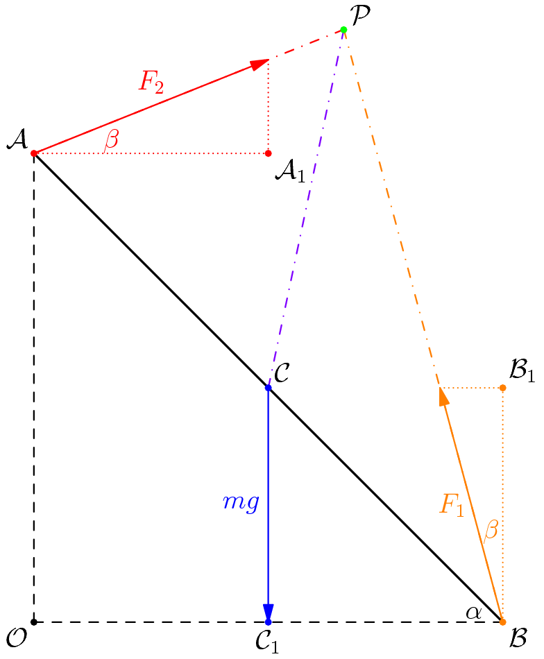
\[|F_i| = \sqrt{f_i^2 + N_i^2} \\ = \sqrt{N_i^2 \tan^2 {\beta} + N_i^2 } \\ = N_i \sec{\beta} \\ = \frac{N_i}{\cos{\beta}} \\\]Furthermore, it is pretty obvious using trigonometry that the angle between $f_i$ and $N_i$ is $\beta$ (convince yourself of this fact)! At the risk of being too thorough, let’s redraw our free body diagram (Some teachers or textbooks call this a vector diagram, a force diagram, or even a force vector diagram! It is, however, the same exact idea) (Not to scale) in terms of the generalized forces $F_i$. We also assign points, because - you guessed it - we’re about to get dirty with some geometry.
\begin{center}
    \begin{asy}
        import graph;
        size(10cm);

        real f(real x)
        {
            return 1 + 0.4 * x;
        }
        path g = graph(f, 0, 0.661);
        draw(g, red+dashdotted);

        real h(real x)
        {
            return -3.731 * x + 3.731;
        }
        path h = graph(h, 1, 0.6611);
        draw(h, orange+dashdotted);

        draw((1, 0) -- (0, 1), linewidth(1));
        draw((1, 0) -- (0, 0), dashed);
        draw((0, 1) -- (0, 0), dashed);
        draw((0.5, 0.5) -- (0.661, 1.264), purple+dashdotted);

        draw((0, 1) -- (0.5, 1.2), arrow = Arrow, red);
        draw((0, 1) -- (0.5, 1), red+dotted);
        draw((0.5, 1) -- (0.5, 1.2), red+dotted);
        label(("$F_2$"), (0.25, 1.11), N, red);
        label(("$\beta$"), (0.13, 1.0275), E, red);

        draw((1, 0) -- (0.866, 0.5), arrow = Arrow, orange);
        draw((1, 0) -- (1, 0.5), orange+dotted);
        draw((0.866, 0.5) -- (1, 0.5), orange+dotted);
        label(("$F_1$"), (0.94, 0.25), W, orange);
        label(("$\beta$"), (0.975, 0.15), N, orange);

        draw((0.5, 0.5) -- (0.5, 0), arrow = Arrow, blue);
        label(("$mg$"), (0.5, 0.25), W, blue);

        dot((1, 0), orange);
        dot((1, 0.5), orange);
        dot((0.5, 0.5), blue);
        dot((0.5, 0), blue);
        dot((0, 1), red);
        dot((0.5, 1), red);
        dot((0, 0));
        dot((0.661, 1.264), green);

        label(("$\alpha$"), (0.975, 0.02), W);

        label(("$\mathcal{O}$"), (0, 0), SW);
        label(("$\mathcal{A}$"), (0, 1), NW);
        label(("$\mathcal{B}$"), (1, 0), SE);
        label(("$\mathcal{A}_1$"), (0.5, 1), SE);
        label(("$\mathcal{B}_1$"), (1, 0.5), NE);
        label(("$\mathcal{C}$"), (0.5, 0.5), NE);
        label(("$\mathcal{C}_1$"), (0.5, 0), S);
        label(("$\mathcal{P}$"), (0.661, 1.264), NE);
    \end{asy}
\end{center}

Now, put aside forces for a bit and think instead about torque. On the downlow, the goal of this problem is to explore as many shortcuts as possible. So, here’s another one. The torque goes to zero, if the point about which we take the torques is collinear with points $\mathcal{A}$ and $\mathcal{B}$. We denote this point as $\mathcal{P}$.
For this next bit of argument, you might need to flip back to a geometry textbook. We first show that $\angle \mathcal{APB} = \frac{\pi}{2}$.
\[\angle \mathcal{APB} = \pi - \angle \mathcal{PAC} - \angle \mathcal{PBC} \\ = \pi - \left ( \alpha + \beta \right) - \left ( \frac{\pi}{2} - \alpha - \beta \right) \\ = \frac{\pi}{2} \\\]Using Thales’s Theorem, we can see that $\mathcal{P}$ is on the circle with diameter $\mathcal{AB}$. Therefore, $\triangle \mathcal{PCB}$ is isosceles, since $\mathcal{PC}$ and $\mathcal{CB}$ are radii of the same circle. Therefore,
\[\angle \mathcal{PCC}_1 = \angle \mathcal{BCC}_1 + \angle \mathcal{PCB} \\ = \left ( \frac{\pi}{2} - \alpha \right) + \left ( \pi - 2 \angle \mathcal{PBC} \right ) \\ = \frac{3 \pi}{2} - \alpha - 2 \left ( \frac{\pi}{2} - \alpha - \beta \right) \\ = \frac{\pi}{2} + \alpha + 2 \beta \\\]To compute the torque due to gravity, which is applied a distance $\frac{L}{2}$ away from $\mathcal{P}$, we see that the angle between the direction the force is applied and $\mathcal{PC}$. The torque is therefore,
\[\tau = mg \frac{L}{2} \sin{\left (\frac{\pi}{2} + \alpha + 2 \beta \right)} = \frac{1}{2} mgL \cos{\left ( \alpha + 2 \beta \right)}\]We want to make this zero using the appropriate choice of $F$, our force that we will apply. To minimize $F$, we want to make the point of application of the force be as far from $\mathcal{P}$ as possible. Moreover, we want to make the direction of the force perpendicular to the line connecting the point of application to $\mathcal{P}$.
We essentially have two choices of lengths: $\mathcal{AP}$ or $\mathcal{BP}$. Using the law of cosines on $\triangle \mathcal{PBC}$ and $\triangle \mathcal{PCA}$ (please actually do this computation!),
\[\mathcal{BP} = L \cos{\left ( \alpha + \beta \right)} \\ \mathcal{AP} = L \sin{\left ( \alpha + \beta \right)} \\\]We compare these two lengths and observe that $\mathcal{BP}$ is longer when $\alpha + \beta < \frac{\pi}{4}$ and vice versa. Therefore, the solution for $F_{\text{min}}$ is $\frac{\tau}{\ell_{\text{max}}}$, which we can write as
\[F_{\text{min}} = \begin{cases} \frac{1}{2} mg \frac{\cos{ \left ( \alpha + 2 \beta \right)}}{\cos{\left ( \alpha + \beta \right)}}, 0 \leq \alpha + \beta \leq \frac{\pi}{4} \\ \frac{1}{2} mg \frac{\cos{ \left ( \alpha + 2 \beta \right)}}{\sin{\left ( \alpha + \beta \right)}}, \frac{\pi}{4} \leq \alpha + \beta \leq \frac{\pi}{2} \\ \end{cases}\]Note
We know that $\alpha, \beta \in \left [0, \frac{\pi}{2} \right]^2$ (think about this!). It is very possible that $\alpha + 2 \beta \geq \frac{\pi}{2}$ given the range for each degree of freedom. This, in turn, would cause the quantity $\cos{\left ( \alpha + 2 \beta \right)}$ to be negative, causing the torque due to gravity to be negative, and as a result causing the force applied to be against the direction it should be facing. This is indicative of a contradiction, so we can assume $\alpha + 2 \beta < \frac{\pi}{2}$. However, if $\alpha$ were to increase, then $\mathcal{C}$ would rise, which would be an energetic paradox (think as hard as you can about this!). The only conclusion then is that $\alpha$ cannot rise without falling back to a safe value.